Functional parts fail in predictable ways—usually at the interface between infill struts, perimeters, and the way loads travel through layers. If you’re trying to improve stiffness, reduce wobble, or prevent cracks from growing, the infill pattern you choose (gyroid vs cubic) changes the way stress is distributed inside your part.
This guide compares gyroid and cubic infill for typical functional use-cases: lightweight brackets, snap-fit frames, and housings. You’ll learn how each pattern behaves under bending, vibration/fatigue, and layer-direction loading, and how to tune density and wall thickness so your design holds up over time.
Gyroid Infill for Functional Parts

Strengths
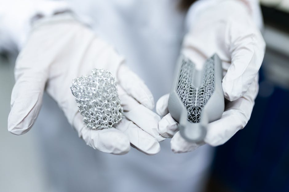
Gyroid tends to deliver strong stiffness-to-weight because the curved geometry spreads load across many directions instead of concentrating it along straight edges. That matters for functional parts that experience mixed forces—like brackets that both bend and twist, or housings that see vibrations.
Because the lattice has no “hard corners” the way orthogonal cubic cells do, it can feel more stable under repeated loading. In practical terms, this often means fewer sharp stress risers where cracks can start, especially when the load direction changes slightly during use.
Gyroid also plays well with thin-to-moderate perimeters. When perimeters do the heavy lifting along the outside, the infill fills in with a structure that doesn’t drastically interrupt the stress flow.
Weaknesses
The same smooth geometry that distributes stress can also make gyroid less efficient in very specific, single-direction loading scenarios. If your part mainly sees one dominant force direction and you’re trying to maximize stiffness per unit filament, a more “directional” or orthogonal lattice can sometimes be easier to optimize.
Also, gyroid can be slightly more demanding to print cleanly depending on your slicer settings and printer capability. If the nozzle has trouble maintaining consistent extrusion on fine curved lines, the infill may become rougher than expected, which can reduce effective strength.
Finally, gyroid can increase print time at comparable densities, since it often has more complex toolpaths than simpler cubic grids.
Cubic Infill for Functional Parts

Strengths
Cubic infill is straightforward for slicing and often easier to print consistently. The geometry forms clear load paths aligned to the grid, which can help when a part’s load direction lines up with those axes.
Because the struts are more “blocky,” cubic infill can be useful when you need predictable stiffness in a specific plane. For example, certain bracket-like parts that primarily experience bending in one direction can benefit from how stresses travel through straight segments.
Cubic also tends to be easier to reason about when you’re scaling density: raising infill percentage generally increases the number of supporting struts in a more obvious, incremental way.
Weaknesses
Cubic infill introduces more corner-like transitions. Those corners can act as stress concentrators under cyclic loading, especially if your part flexes repeatedly (fatigue) or experiences impacts.
Another common downside is anisotropy. Since cubic cells align to the grid, stiffness can vary depending on load orientation. If your part twists, loads at angles, or flexes in multiple directions, the “grid-aligned” structure may not spread stress as evenly as gyroid.
Cubic can also create stronger “layer-to-layer” planes depending on how your slicer generates the pattern and how your printer handles bridging of small gaps. If your part sees loads that try to peel layers apart, the way the lattice intersects those planes matters.
In short: cubic infill can be great for predictable, axis-aligned stiffness, but gyroid usually wins when loads are multi-directional or fatigue-critical.
Match the Pattern to Your Functional Use Case
Choosing between gyroid and cubic comes down to how your part loads in real life—especially across layers.
Lightweight brackets
Brackets typically experience bending and twisting. Even if the primary load is “mostly downward,” the bracket often flexes, and small angular changes during use add multi-directional stress.
Gyroid infill is usually the safer default here: it distributes stress through curved struts and avoids many pronounced internal corners. That can improve resistance to gradual crack growth if the bracket sees vibration or repeated handling.
Cubic can work if the bracket’s load and stiffness goals are aligned with the printer axes and you’re optimizing for faster prints or simpler tuning. If you go cubic, orient your part thoughtfully and consider whether the load will introduce twisting.
Snap-fit frames
Snap-fits are fatigue machines. They flex during assembly and then can flex again over time with use, temperature changes, and user force.
Gyroid infill often performs better in fatigue-prone parts because the lattice geometry reduces sharp stress risers and spreads strain through a 3D network. Pair that with correctly sized flex features: infill can help, but if the snap arm is too thin or too stiff, it will crack where the geometry concentrates strain.
Cubic infill may be more sensitive to crack initiation at internal corners under repeated flexing. If you use cubic for snap-fit frames, it’s especially important to avoid under-extrusion and to ensure the flex region is supported with enough surrounding material (perimeters plus infill), not just a low infill percentage.
Layer-load matters too. Snap-fits often peel or bend across layer boundaries depending on the print orientation. Choose an orientation so the primary bending plane doesn’t force layers to separate.
Housings and covers
Housings experience vibration, fastening forces, and sometimes localized impacts (dropping tools, tightening screws, thermal expansion).
Gyroid infill generally helps with vibration and multi-point loading because it provides a more uniform internal support network. That’s useful when fasteners apply force at angles and when the cover flexes slightly during real-world use.
Cubic can be fine for simpler housings where loads are fairly predictable and aligned. But if the housing flexes in different directions—or you expect long-term cyclic loads—gyroid’s stress distribution tends to be more forgiving.
Tune Infill Density for Stiffness and Fatigue (Practical Steps)
Pattern choice matters, but infill density and perimeter strategy decide whether the part actually gets stronger or just gets heavier.
Use these steps to dial in your functional print without over-spending on filament or print time:
- Start with more perimeter than infill. For many functional parts, perimeters control buckling and surface stiffness, while infill mainly supports the internal volume.
- Pick the pattern based on load direction complexity. Use gyroid for mixed-direction bending/twist and fatigue. Use cubic when loads are mostly axis-aligned and you want simpler tuning.
- Increase infill until motion reduces noticeably. If the part still flexes, raise density gradually; if weight climbs fast without stiffness gains, stop and revisit geometry (thickness, ribbing, fillets).
- Check for layer-peel risk. If your loads try to separate layers (peeling/overhang shear), don’t rely on infill alone—print orientation and interface strength matter at least as much.
- Stress-test the weak feature, not the bulk. For snap-fits, evaluate the flex region and its immediate neighbors. For brackets, flex the corner that sees highest bending moment.
- Re-print only after adjusting one variable at a time. Change pattern or density first, measure the result, then move to perimeter or orientation. That keeps your improvements repeatable.
A final practical rule: if the part is fatigue-critical (snap-fits, vibrating mounts, repeatedly flexed arms), bias toward gyroid and pair it with robust perimeters and a print orientation that resists layer separation.
For more rigid, axis-aligned functional parts where loads are predictable and print consistency matters most, cubic infill can be a workable choice—especially when you don’t need complex stress distribution.
The most reliable next step is to run a small test: print the same geometry with gyroid and cubic at the same infill percentage, then compare how each one flexes at the feature that’s most likely to fail over time. That quick feedback usually beats guessing based on infill percentage alone.
PriceIt3D may earn a commission when you buy through links on this page, at no extra cost to you. Affiliate notice.