
Infill isn’t just “filling”—it decides how forces travel through your part. The right pattern and density can make a functional print feel rigid under load, resist wobble from vibration, and avoid wasting hours on unnecessary material.
This guide walks you through choosing common infill patterns (gyroid, cubic, grid, triangles), dialing in infill density, and balancing infill with wall thickness so you get strength where it matters.
Match Infill Strategy to the Way Your Part Is Loaded
Use this quick workflow before you touch pattern or density:
- Identify the load direction and the “weak feeling” you’re trying to fix (bending, rattle, flex, or cracking).
- Decide whether the critical strength should come from the shell (walls) or from the inside structure (infill).
- Choose a pattern that transfers stress efficiently in the directions your part experiences force.
- Pick a starting density based on how stiff you need the part to be, not just how “strong” you hope it is.
- Set wall count (perimeters) and top/bottom layers first, because they largely control stiffness and surface strength.
- Tune infill density next, increasing it only if the shell can’t carry the load.
- Print a small test piece (or a section) that replicates the load direction and geometry.
- Keep a simple notes trail (pattern, density, wall count) so you can iterate quickly.
If you follow only one idea: shells and top/bottom layers usually do more for real-world strength than piling on infill density.
Pick an Infill Pattern That Fits Your Stress Type

Gyroid
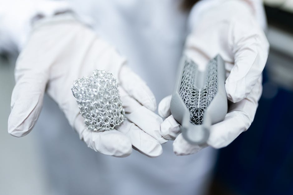
Gyroid infill forms a smooth, continuous structure that tends to distribute stress in multiple directions. That makes it a strong choice when your part will see vibration or forces that shift around (for example, a bracket that rattles or a housing that experiences alternating loads).
What it means for performance:
- Good stiffness without needing extremely high density, because the geometry supports force in more than one direction.
- Better resistance to “wobble” because it’s less likely to create large, easy-to-bend planes inside the part.
Trade-offs to watch:
- It may print slower than simpler, more open patterns because the toolpath can be more intricate.
- You still need enough walls for bearing strength where screws, inserts, or mounting surfaces matter.
Cubic (and similar lattice blocks)
Cubic-style infill creates a repeating network of connected struts. It generally performs well for supporting loads that benefit from a more “regular” internal framework.
What it means for performance:
- Often feels more rigid than low-density grid patterns because the interior connects in a structured way.
- Can be a good compromise when you want strength in multiple directions but don’t want the complexity of gyroid.
Trade-offs to watch:
- At lower densities, some cube-like structures can allow more flex along specific planes, which shows up as rattling under vibration.
- Higher densities can cost time quickly since the number of internal intersections increases.
Grid (rectilinear)
Grid infill is easy to understand: it’s rows and columns, sometimes with alternating directions. That simplicity makes it fast to slice and can print efficiently.
What it means for performance:
- Great for prototypes and prints where you mainly need light support.
- At higher densities it can become stiff, but at lower densities it can act like a set of bending beams that may flex under vibration.
Trade-offs to watch:
- Direction matters. If your part loads align with the grid’s weak orientation, you’ll see flex or rattle even if the density looks “fine” in the slicer.
- For impact-heavy use, very low infill densities can allow stress concentrations to propagate through the open internal spaces.
Triangles (and triangle-based infill)
Triangle-based infill forms internal planes connected through diagonals. That diagonal geometry can be efficient at resisting shear and bending, because triangles are naturally stable shapes.
What it means for performance:
- Often provides strong stiffness in certain load directions, especially when the part geometry and infill orientation line up with the forces.
- Can be a good option when you’re chasing a “no flex” feel in a directional bracket or reinforcement.
Trade-offs to watch:
- It can be less forgiving than gyroid for multi-directional vibration, because the network may favor particular directions depending on how your slicer places the pattern.
- If the load direction changes (or is unknown), you may need to test or pick a more direction-agnostic pattern.
Choose Infill Density for Stiffness, Not Just “Strength”
Infill density is a volume percentage, but the practical outcome is stiffness and how well the internal network restrains deformation. That matters because many “failures” in real prints aren’t sudden breaking—they’re flex, wobble, slow cracking from repeated stress, or layers separating from stress concentration.
A useful way to think about density:
- Low density: internal structure is mostly support. The part relies heavily on walls and top/bottom layers for rigidity.
- Medium density: internal infill starts doing real work—reducing bending deflection and improving vibration resistance.
- High density: approaching “solid” behavior, but with rapidly increasing print time and material use.
Practical density starting points (treat these as ranges)
- Prototypes and light-duty parts: lower densities work when the shell does the heavy lifting.
- Functional parts that must resist flex or rattle: move into medium density so the infill can restrain deformation between wall layers.
- Near-solid feel: use higher density only when walls alone can’t control deflection.
Why density alone can disappoint:
- If walls are too thin, increasing infill density may not fix screw-area strength, mounting stiffness, or surface-related failure.
- If your infill pattern creates weak planes, density may increase material but still leave deformation paths.
A good rule of thumb is to increase walls first for stiffness at the locations that take load (mount points, beam faces, bearing surfaces). Use infill density to tune the “inside” behavior after the shell is right.
Balance Infill Density with Wall Thickness and Top/Bottom Layers
Wall thickness (number of perimeters) and top/bottom layers affect strength in a more direct way than many people expect.
Here’s how the interaction usually plays out in real-world parts:
- Walls carry bending loads like the flanges in an I-beam. Thicker walls can dramatically reduce flex because they constrain the outer shape.
- Top/bottom layers resist compression and help prevent layer-related cracking when a load presses into the part.
- Infill fills the interior and reduces how much the walls can bow between their anchors.
What to do first (so you don’t waste print time)
- Increase perimeter count when you see deflection on the outside, cracks that start near edges, or loose mounting.
- Add top/bottom layers when you’re getting crushing, splitting, or delamination under compressive loads.
- Increase infill density when the shell looks sound but the part still feels like it “rings” or wobbles under vibration.
How pattern choice changes this balance:
- Gyroid often improves vibration resistance with less density because its continuous geometry restrains motion in multiple directions.
- Grid often benefits more from wall-focused reinforcement; density helps, but it can still flex along grid planes unless you push it higher.
- Cubic and triangle infills can be effective, but they still depend on shell thickness for real mounting strength.
One more detail that matters: infill-to-wall bonding. If your infill density is high but your extrusion is inconsistent or your bonding between lines is weak, the interior can’t transfer load efficiently. In practice, consistent extrusion and good layer adhesion often outperform “more infill.”
Test Like an Engineer: Use Small Prints to Lock In the Right Settings
You don’t need to run expensive trials for every project, but you do need feedback that matches your failure mode. A small test can save hours of full-size printing.
A good test strategy focuses on the variable you’re changing:
- Keep wall thickness and top/bottom layers constant while you compare patterns or densities.
- Test in the same orientation as the final part. Many stiffness issues are orientation issues.
- Evaluate both static stiffness (does it bend?) and dynamic behavior (does it rattle after being tapped?).
What you’re looking for during testing:
- If the part bends, add shell reinforcement before adding lots of infill.
- If the part rings or wobbles, switch to a more vibration-friendly pattern (gyroid is often the first place to try) and then adjust density.
- If you see cracking starting near edges or around features, increase perimeters and top/bottom layers at those regions.
A simple way to converge quickly:
- Start with a medium density and a gyroid (or another direction-appropriate pattern), confirm stiffness, then reduce density if it’s overkill.
- Or start with your intended pattern at a lower density and increase only until the part stops flexing or rattling.
When you choose settings this way, you’re not just chasing a “stronger number”—you’re matching internal geometry and shell structure to how loads actually travel.
If you want the most reliable starting point for strength plus vibration resistance, set solid walls (and enough top/bottom coverage), then use gyroid infill at a medium density. Increase density only if the shell is already doing its job but the interior still allows deformation.
PriceIt3D may earn a commission when you buy through links on this page, at no extra cost to you. Affiliate notice.